Introduction
Fiber-optic beam delivery has many advantages over free-space laser diodes. Not only do fiber-coupled laser diodes provide the ability to deliver light to the desired location efficiently, but they also have a wide variety of other optical advantages. For example, depending on the geometry of the fiber’s core, it can act as both a spatial filter (single-mode) or a beam homogenizer (multimode). Fiber coupling also has many mechanical advantages, such as being able to swap out lasers without the need to realign the entire system. Lastly, by fiber coupling a laser, it makes it far easier to combine the laser with other fiber optic components, such as amplifiers, modulators, or detectors. These advantages are why approximately half of the laser diodes offered at RPMC Lasers are fiber-coupled.
There are two main categories of fiber-coupled laser diodes, pigtailed and detachable. The pigtailed approach provides significant advantages when it comes to alignment stability, mainly when dealing with single-mode fibers which, typically have a core diameter of less than 10 microns. By comparison, it is impossible to ensure that detachable fiber-optics will line up in the same spot, each time the fiber is connected. Therefore, reducing the overall coupling efficiency of the system. However, unless the pigtail is fusion spliced to another fiber, for both pigtailed and detachable fibers, it is required that at least one end of the cable be terminated with a fiber-optic connector. As a result, it is essential to understand the different types of fiber connectors used with fiber-coupled diode lasers as well as their pros and cons.
Common Fiber Connectors
Modern fiber-optic connectors are plugs with a protruding ferrule which serves to both secure and align the fiber. Figure 1 below shows a schematic cross-section of a connector ferrule, demonstrating how it can be used to self-center the fiber. The tapered inner section of the ferrule allows for the fiber to self-center during the gluing and curing process. Manufacturers typically accomplish this by injecting a drop of thermal epoxy into the larger opening in the rear of the connector. They then feed the fiber through the ferrule, ensuring only a small portion (typically a millimeter or less) of the fiber, along with a small bead of epoxy, is exposed. After the epoxy has cured and any excess fiber has been cleaved off, they polish the tip of the ferrule using finer and finer grit sandpaper until the surface of the fiber has an optical quality finish. Depending on the connector style and fiber type being used, there may be slight variations between processes. However, all fiber optic connectors are glued and polished in roughly this manner.
 Figure 1: Schematic cross-section diagram of a typical fiber optic ferrule.
All fiber-optic connector technology has come to the laser community via the telecom industry, which has abbreviated names such as LC, ST, SC, FC, FDDI, ESON, and SMA to name a few. While there are nearly limitless options for fiber-connectors, the vast majority of fiber-coupled lasers use one of two main designs. The two main options are the FC connector, which stands for “fiber connector” or “ferrule connector” and the SMA905 connector, where SMA stands for “Subminiature A,” and 905 denotes a 1/8th-inch diameter ferrule. SC and ST connectors, which stands for “subscriber connector” and “straight tip” are also occasionally used with fiber-coupled laser diodes. Still, these are simply variants of the FC connector design, which allow for quick connection and disconnection. So, in this paper, they will be treated as a subset of FC connectors.
SMA905 Connector
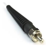
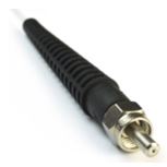
While most in the telecom industry consider the SMA905 connector to be obsolete, they are still the most commonly used fiber connector for high power and large core fiber-coupled lasers. The SMA905 connector, shown in figure 2 below, is a relatively simple design, consisting of a stainless-steel metal ferrule and a threaded screw cap. The inner diameter of the ferrule in a SMA905 connector can be drilled out, allowing it to support fiber optics with cladding diameters ranging from 125 microns to over 1000 microns. While the simplicity of this design makes fabrication quite easy, there are tolerancing stack-ups that make precision alignment next to impossible. For example, the fact that this threaded connector isn’t keyed, means that every time it is removed and reinserted, there will be an uncertainty in alignment. Secondly, the mechanicalprocess of boring out the fiber feedthrough is inherently sloppy as well. A typical SMA905 ferrule, for a 125-micron cladding diameter fiber, is specified to have a feedthrough diameter of 126 -0/+4 microns. Therefore, even assuming that two SMA905 connectors are entirely centered on each other (which they often are not), the fiber cores can be offset from each other by as much as 10 microns. For a 105-micron core fiber, this can result in a 10% offset in each fiber, causing up to 20% coupling loss, which depending on the application, may or may not be tolerable. However, if the same connector was used with a 9-micron core single-mode fiberoptic, the fiber centration alone can result in zero coupling between the two fibers. Therefore, one should never use a SMA905 connector for single-mode fiber coupling.

Figure 2: SMA905 Fiber-Optic Connector
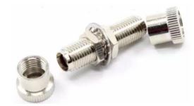
To better understand the pros and cons of SMA905 connectors, it is useful to take a moment and explore how they couple together. The first thing to note, when combining two SMA905-terminated fiber-optics, is that they are not designed to be in physical contact with each other. While this dramatically simplifies the construction of an SMA to SMA coupler to a simple threaded hollow tube, as shown in figure 3, it also increases the likely hood of fiber core mismatch. As a result, it is easy to understand that the general rule of thumb is that SMA905 connectors should only be used for multimode fibers, with core diameters greater than 200 microns or larger. This way, the overall loss from the connector slop is minimal.
 Figure 3: SMA905 matting connector.
Additionally, SMA connectors are also commonly used in applications where coupling free-space laser light into a fiber-coupled bulkhead, such as in the two examples shown in figure 4. In this case, the non-contact nature of the SMA905 connector makes it easier for coupling large-core single emitters, or geometrically beam-combined multi-emitters into a single large core detachable fiber-optic cable.
 Figure 4: Examples of bulkhead connectorized multimode lasers for detachable SM
To continue please fill out the form below

Figure 1: Schematic cross-section diagram of a typical fiber optic ferrule.

Figure 3: SMA905 matting connector.
Figure 4: Examples of bulkhead connectorized multimode lasers for detachable SM

 SHIPS TODAY