RPMC Lasers has published several different pieces of technical content on various LIDAR applications. Some of our more recent posts include a white paper titled “Single Frequency Fiber Lasers for Doppler LIDAR,” and a blog post on the use of aerial LIDAR in bathymetry. LIDAR is quickly becoming one of the most rapidly growing sectors of the overall laser market. In fact, Market Insider recently reported that “The market for LIDAR is expected to grow double in size in the next five years.” In the same article, published in May of 2019, they went on to point out that the primary reason for this rapid growth “… is derived from the increasing spaces of self-driving vehicles as well as enhanced driving assistance.” For this reason, we have decided to dedicate this application note to look at exactly why LIDAR is so essential for autonomous cars and the different types of laser systems utilized currently.
Why Lidar for Self Driving Cars?
Self-driving cars need to find some way of emulating the cognitive capacity of a typical human driver, and while much of the press on this subject focuses on advancements in artificial intelligence (AI) without proper input data, these AI systems are useless. Hence, all self-driving cars require a “set of eyes,” which are as good or better than those of a human to provide the necessary information for the AI to control the vehicle. Over tens of thousands of years, the human eye has evolved fantastic depth perception, angular resolution, and the ability to adjust focus between near- and far-field. Meaning that whichever artificial means that are employed by the vehicle for simulating the human eye, must be able to accomplish all these tasks and more. Currently, the leading candidates for this are camera technology, radar, and LIDAR. In the chart below, Jake Li of Hamamatsu illustrated the pros and cons of all three approaches rather eloquently in his talk on the matter at the CLEO conference.

As Jake Li shows in this chart, there are advantages and disadvantages to all three methods, but LIDAR offers by far the most superior angular resolution due to the extreme coherence and directionality of lasers. The question then becomes, “why is angular resolution so important?” The reason for this is quite simply that it is the only way to ensure that like the human eye, the imaging system will be able to provide reliable information in both the near- and far-field. When coupled with the fact that LIDAR is relatively insensitive to the ambient lighting conditions, which as any driver would know can vary wildly under normal driving conditions, it is clear to see why LIDAR provides the highest quality input data for the car’s AI.
Time-of-flight (TOF) vs. Frequency Modulation (FM)
It would be neglectful not to mention that there are still a large number of technological and economic hurdles which engineers are actively working on in automotive LIDAR. These hurdles include things such as beam steering, optical design, and detector sensitivity. However, from the laser source perspective, one of the biggest questions is whether to use time-of-flight (ToF) or frequency modulation (FM). We have discussed both of these LIDAR techniques in great detail in prior publications, so for the sake of brevity, we will limit ourselves to a brief review of the two in this application note, a much more detailed explanation of the two methods is available in the white paper titled “Single Frequency Fiber Lasers for Doppler Lidar.“
Principal of Time-of-flight (TOF) LIDAR for Distance Measurement
TOF LIDAR follows the principle that you can determine the distance between two objects by measuring the amount of time between when a pulse of light is transmitted, and the light reflected off of that object is detected. Since the speed of light in air is a constant, it is rather simple to mathematically deduce the distance that the light traveled over time. While simple and effective this method does have two significant drawbacks, first it cannot determine the speed at which the object is moving relative to the transmitter/receiver and secondly the distance resolution is dependent on the lasers pulse width. For example, since light travels at approximately one foot per nanosecond, if utilizing a 10 ns laser pulse, a LIDAR system would have a maximum distance resolution of 10 feet. With long-distance ranging this isn’t a big issue, but for automotive LIDAR 10 feet is nearly a car length. Therefore, short pulse sub-nanosecond lasers are required for all automotive ToF LIDAR systems. The downside with this is that typically the shorter the pulse width, the lower the pulse energy of the laser, and only a tiny percentage of the transmitted light in a LIDAR system makes it back to the receiver.
Principal of Frequency Modulated (FM) LIDAR for Distance and Speed
By contrast, frequency modulated (FM) LIDAR uses a continuous wave laser, where the laser’s frequency is varied in a repeating pattern. As a result, the laser’s distance resolution is no longer dependent on the lasers pulse width but instead on the bandwidth of the frequency modulation. While there are many different forms of FM LIDAR signals, they are all typically processed through a cross-correlation method, like match filter processing. In layman’s terms, this means that a small portion of the laser signal is split off and used as the “filter,” which is used to interfere with the return signal. Due to the time delay between the roundtrip signal and the filter, the two beams will destructively interfere at all points in time except at the round-trip times between the transmitter and receiver. Not only do FM LIDAR signals provide distance information, but since you are using a continuous wave laser source, it also allows for the determination of frequency changes in the return signal due to Doppler shifting. By measuring the Doppler shift, you are now able to measure the distance and position of the target object at the same time. The figure below shows an example of how both the time shift (t) and Doppler shift (Δf) can be determined using a repeating linear frequency modulation (LFM) pattern.

Single-Frequency – The Commonality Between Various Forms of FM LIDAR
It is essential to point out that LFM is not the only possible FM LIDAR waveform. Lidar systems have also been known to employ non-linear frequency modulation, sparse frequency modulation, Costas matrix encoding, and even pseudo-random phase noise. Regardless of the which FM LIDAR waveform is utilized they all have one thing in common, they require an extremely narrow linewidth laser source. This arises from the fact that you cannot precisely modulate the frequency of the laser light if the laser’s frequency is drifting over time. While there have been some cases where single frequency diode and diode-pumped solid-state (DPSS) lasers have been used for LIDAR, the community as a whole has settled on the single-frequency fiber lasers as the ideal light source.
Advantages of Fiber Lasers for LIDAR Applications
As discussed in our previous white paper, fiber lasers have several advantages over traditional DPSS lasers all of which derive from the geometry of the fiber optic itself, namely the innate ability to have an extremely long single-mode optical cavity. This geometry allows for the production of either high-pulse energy, single-mode q-switched lasers, or extremely narrow band lasers with near-perfectly single-frequency output. Commercially available erbium (Er) doped fiber lasers lase at approximately 1550 nm, which corresponds to the peak absorption band of water making them “eye-safe” which is critical for the deployment of many LIDAR systems. Lastly, these devices are ideal for incorporation with Er-doped fiber amplifiers (EDFAs), which were initially designed for long haul telecommunications, to boost the signal strength for long-range applications.
How Can RPMC Help?
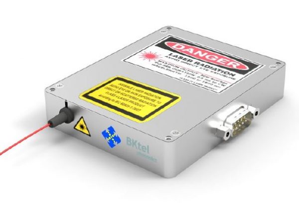
Here at RPMC lasers, our partnership with BKtel allows us to offer all three of these product lines, allowing us to support the automotive LIDAR industry fully. One example is the HFL series of 1550 nm high power pulsed fiber lasers, which is capable of producing 4W of average power with a 400 ps pulse width and a pulse repetition rate up to 2 MHz. Another example is the UHPOA-L ultra-high-power optical amplifier, which offers up to 10 watts of output power with only 0.5 ps of mode dispersion. But, perhaps the most impressive LIDAR laser source from BKtel is the LRL2 single-frequency fiber laser. The LRL2 provides a perfect TEM00 output beam with up to 1 W of output power and a linewidth of 10khz. The LRL2 has an operating range from 0˚C to 65˚C, with a wavelength drift of only 0.1 pm/˚C, and extremely low relative intensity (RIN) noise. Not only are the optical characteristic of these lasers from BKtel ideal for LIDAR signal generation; their compact, energy-efficient, and rugged designs make them ideal for integration in LIDAR systems in the harshest of environments.

As the LIDAR market continues to grow, especially in the automotive sector, RPMC will be here to help provide the industry with the most advanced fiber laser and amplifier OEM modules available. For detailed technical specifications on any of the products we offer from BKtel click here or talk to one of our laser experts today by emailing us at info@rpmclasers.com.

 SHIPS TODAY