Whether a diode laser is a traditional monolithic design or utilizes an external cavity configuration, the laser light must still propagate through the diode’s PN-junction via a ridge waveguide. As a result, the beam profile of edge emitting diodes is unique when compared to all laser sources because of the asymmetric geometry of this optical cavity. This issue often leads to confusion about how to properly integrate open beam laser diodes into your system, so to help this blog aims to elaborate on the information provided in our Lasers 101 section by explaining the physical principles. We will start by briefly reviewing PN-junctions, and then we will explore the role of the ridge waveguide. Finally, we will conclude with an overview of common optical tricks for dealing with asymmetric laser beams.
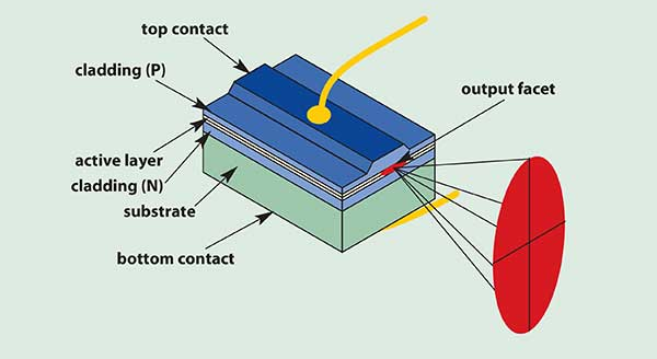
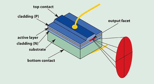
An in-depth analysis of the physics of PN-junctions isn’t necessary to understand the beam properties, but it is essential to realize that this junction, which is only about 1 micron in thickness is the only part of the diode where electron-hole recombination is possible. As a result, no matter how powerful the laser diode is, this thin layer is the single location where light generation and amplification is possible. Therefore, it is critical to ensure that all of the laser light is tightly contained within the PN-junction. This is accomplished by etching a ridge into the top layer of the diode which creates a waveguide due to the extreme difference in index of refraction of the semiconductor (~3.5) and the air (~1.0) interface. If this ridge is significantly narrow as to only allow a single spatial mode to propagate through the waveguide, for example, 3 microns at 785nm, then it will result in a single mode laser. However, this limits the total volume of the diode’s laser cavity and increases the power density at the facet, limiting the maximum laser power. For higher power applications the diode ridge width is typically expanded to approximately 100 microns to increase the cavity volume and decrease the front facet power density. For extremely high-power applications multiple waveguides can be placed on the same diode producing an array of single emitters on one diode bar.
Since in all of these cases the laser light is contained, when it is emitted it diffracts forming a highly divergent beam. Additionally, due to the asymmetric nature of the geometry, the axis of the beam perpendicular to the PN-junction diffracts and follows a higher divergence angle than the axis parallel to the PN-junction resulting in an elliptical beam as shown in the figure below. These two axes are therefore labeled as the fast-axis and slow-axis respectively resulting in an elliptical beam. Now, in all cases, the fast axis of the beam will only contain a single longitudinal mode because the beam is contained within such a narrow cavity. Depending on the ridge width and the laser wavelength the slow axis can include either one or multiple modes. In the case of diode bars, the modes from each emitter tend to mix and form a reasonably homogeneous output beam, but for multi-mode single emitters the beam often contains “hot spots” and “cold spots” which can be problematic for some applications.

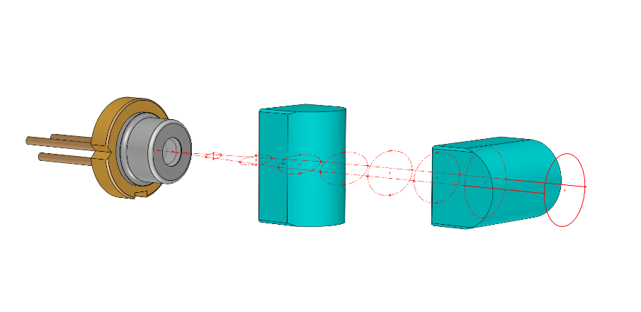
For some application such as laser pointers this elliptical beam shape is perfectly fine and as such only a single optic is necessary for culminating the output. This can be accomplished either by utilizing a cylindrical lens which reduces the divergence of the fast axis while allowing the slow axis to pass through unaffected or by using a single aspherical lens. For more advanced applications which require a circular beam cross cylindrical lenses where each lens is chosen to match the numerical aperture of the fast and slow axis can be used as shown in the figure below. While this approach does an excellent job of circularization it often results in a diamond-shaped beam profile due to amplified spontaneous emission, to further improve the beam quality, it is generally preferable to fiber couple the beam and then recollimate the output. For single mode lasers the fiber acts as a spatial filter resulting in a perfect TEM00 output beam, and in the case of multi-mode lasers, the fiber acts as a homogenizer significantly reducing the hot spots and dark spots. All of the optical configurations discussed previously are used with single emitters, but the same principles can also be applied to multi-emitters where large cylindrical lenses or microlens arrays are often utilized.

Talk to a knowledgeable Product Manager today by emailing us at info@rpmclasers.com or by clicking the button below!
Have questions?
Here at RPMC Lasers, we have over 20 years of experience with diode lasers and are readily available to assist you in not only deciding which of our standard off-the-shelf laser diodes are ideal for your application, but we are also able to offer countless custom laser diode packaging configurations with a wide range of integrated optics including all of the designs discussed above. For more information about our wide variety of laser diodes you can click here, and for more information about laser diode fundamentals be sure to visit our Lasers 101 page.

 SHIPS TODAY