In actively Q-switched lasers, the user controls the pulsed laser output, so that no laser pulse emission occurs without providing a proper input signal, aka “the trigger”. Due to the trigger signal propagation through the interface electronics, the Q-switch driver chain, and the laser resonator build-up time, a time delay (Td) is present between the externally supplied trigger signal and the actual laser pulse (nanosecond or picosecond) emitted by the laser source. The Td can show fluctuations if any electronics or optics involved in the pulse generation process have a functional variance in time.
The parameter Td is very relevant in the timing management of some applications. You must consider both the time delay (Td) and a time jitter (Tj), which is a statistical variation of the time delay depending mostly on:
- electrical noise in the trigger-chain
- pulse-to-pulse fluctuation of trigger-chain electrical parameters
- laser pulse build-up time-mechanism and associated fluctuations.
- fluctuation of rising (-falling) edge temporal profile of the trigger signal
Because of the jitter phenomena, the actual value of the time delay is statistically altered. Therefore, the laser pulse emission event happens (in the vast majority of cases) inside a normal time distribution, defined by an average time delay Td and a standard deviation value Tj (i.e 68.2 out of 100 pulses develop in the time interval Td ±Tj).
|
Bright Solutions’ lasers like the Onda, Wedge and Vento are available in a “low jitter” configuration, which minimizes the time jitter Tj (in some cases to 1/10 or even 1/20 of the laser pulse width). This option can be advantageous in applications like Time of Flight (TOF) metering. In these applications, the laser pulse is mainly used to measure a fixed or moving target’s distance. After directing a laser pulse toward the target, an optical detector collects the photons reflected or backscattered from it. Then, the detection electronics count the time between the emission of the laser pulse and the collection of photons coming back from the target. |
 |
Considering that the speed of an electromagnetic wave in air is approximately 3 x 10⁸ m/s, the linear spatial resolution (r) achievable by a 3 ns pulse is of the order of:
r = 3 x 10⁸ m/s x 3 x 10⁻⁹ s = 0.9 m
Modern detection techniques can significantly reduce this figure. If the same electric signal triggers the laser emission and the time counter, jitter will introduce (in 68.2% of the measurements assuming a normal distribution) an error distance De of:
De = ±c (speed of light) x Tj/2
-where c is the speed of light
If the above-defined jitter Tj is in the order of 1 ns, the measurement error could be ±15 cm, which can be excessive for some critical applications.
Configuring lasers in “low jitter” mode, we can reduce Tj for a 3ns-pulse width laser down to ±200 ps or less. Therefore, the error can be reduced five times down to 3 centimeters.
Of course, the user must take care of signal generation in terms of output impedance (50 Ohm) and the sharp and short rising edge of TTL trigger.

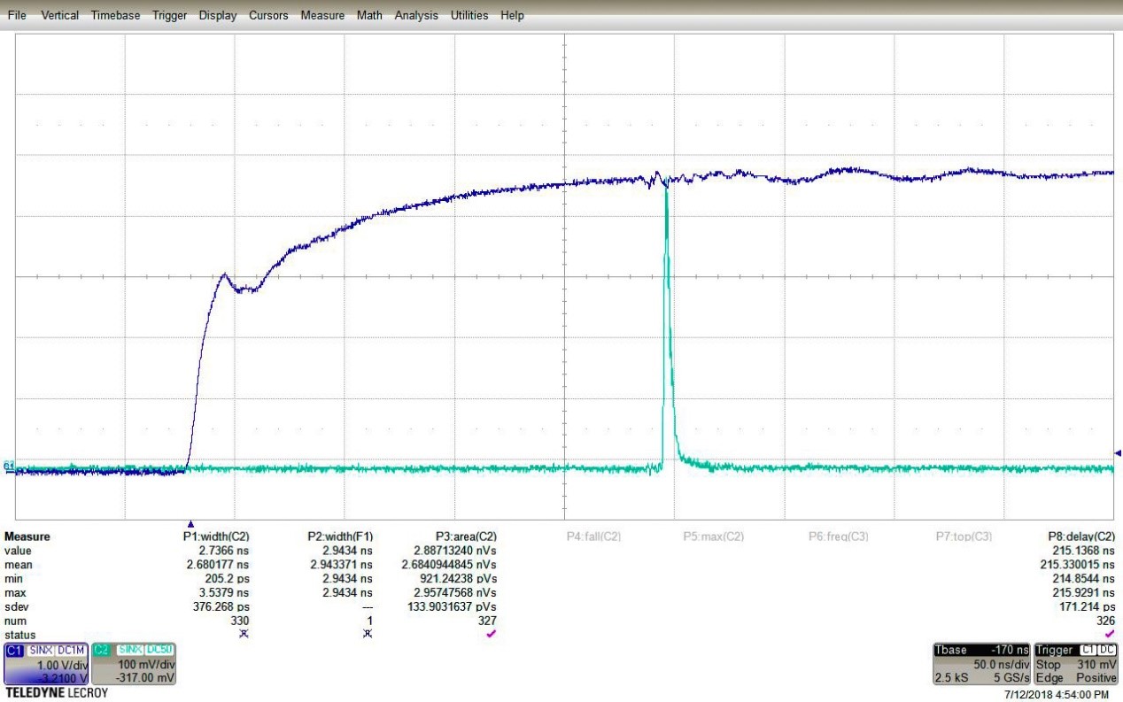
The oscilloscope screenshot above shows the jitter measurement for a Bright Solutions, 2.7ns-long, low-jitter, airborne, LiDAR illuminator. The blue curve is the trigger IN signal, while the green curve is the laser pulse detected by a fast photodiode. The standard deviation of the laser pulse’s delay, with respect to the rising edge of the trigger IN signal, is the jitter.

Looking at measure P8 and its statistics, it turns out that the average delay Td is 215ns (mean of P8), and the jitter Tj is 171ps (sdev of P8), which corresponds to approximately 1/16 of the laser pulse width. Thus, in this specific case the error in the distance measurement is reduced down to about ±2.5cm.
Talk to one of our knowledgeable Product Managers today by emailing us at info@rpmclasers.com or Contact Us with the button below!
Have questions?

 SHIPS TODAY