Electric power is determined by the product of the voltage and current supplied to a device. As a result, when designing an adjustable power supply, one of those two parameters must be variable, and the other constant if you want to be able to tune the power supply to your desired output. These two types of supplies are known broadly as constant current (CC) and constant voltage (CV) output circuits. When driving a laser diode, both CC and CV power supplies have pros and cons, but the rule of thumb is that you should always use a CC supply and never use a CV. To understand why laser diodes shouldn’t be voltage driven, we must first take some time to understand one of the most important characteristics when integrating a diode laser, the LIV plot.
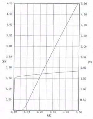
 The LIV plot, which stands for light-current-voltage, provides a single chart that superimposes the measured power vs. current (LI) and voltage vs. current (VI) curves for a given diode laser. The LI curve provides you with the overall efficacy of the diode, which is determined by the slope, in units of W/A. Though often overlooked, the VI is an important parameter when trying to understand the electrical characteristics of the diode. It is essential to note that in a LIV plot, laser diode manufacturers typically put the forward voltage on the y-axis of the plot and the current on the x-axis. This is counter to how most diode VI charts are plotted, which can often lead to confusion for electrical engineers who aren’t accustomed to this configuration. An example LIV plot is shown in the figure below for a laser diode from the RWLD Series.

For this plot, which follows the typical shape for any diode laser, it is clear to see that the relationship between a diode’s current and voltage is extremely non-linear. While, across most of the LI curve, the relationship between output power and current is exceptionally linear. The slope of the VI curve indicates that a small change in voltage results in a massive swing in current. While, in theory, this means that the laser’s output power could be controlled through either current or voltage, the precision that you would need to control the voltage makes a voltage controller virtually impossible. Therefore, it is always best practice to configure your electronic circuit such that the diode laser is current driven. This way, a CC power supply is used, and the voltage is floated accordingly, to provide the best possible control over output power.
While it isn’t necessary to understand the underlying material science, it is prudent at this point to note that when designing laser driver electronics that the voltage of the laser diode is inversely proportional to the laser’s wavelength. As a result, if you are developing (or specifying) your CC power supply, you must make sure that the compliance voltage is large enough to handle the shortest wavelength laser that you plan to use. If not, you end up needing to use different power supplies for each laser.
If you would like to get more detailed information on the laser diodes or laser diode drivers offered here at RPMC Lasers, click here or, you can talk to one of our laser experts today by clicking here, or by calling 1-636-272-7227.

 SHIPS TODAY